
Research candidate
Record official switch, driver and fixture part numbers; collect datasheets, power ratings, firmware requirements and cable instructions.
Reference onlySecure Luma intends to specify only lighting systems whose exact UniFi switch, PoE driver, fixtures, cabling and control platform have passed a documented qualification process. We will not claim a combination is approved merely because its individual products meet published PoE power ratings.
No model-specific UniFi + third-party lighting-driver system has passed a recorded Secure Luma interoperability and pilot test.
Each light/driver/switch combination advances only when the required evidence is recorded. A written compatibility statement and a successful physical test are different milestones.
Record official switch, driver and fixture part numbers; collect datasheets, power ratings, firmware requirements and cable instructions.
Reference onlyObtain written confirmation covering the exact switch-driver combination, firmware and lighting controls; document support limitations.
Confirmation, not testingRun all applicable tests with recorded measurements and evidence. Every critical test must pass; any exception requires explicit sign-off.
Exact tested configurationComplete a controlled pilot, verify code and licensing requirements, review support/warranty and approve the technical release.
Unlock supported pairingAny material change to firmware, switch, PSU mode, LED driver, fixture revision, cable design or lighting-control application may require regression testing and temporary suspension of the approved status.
The manufacturer documents the PoEWit two-panel kit with a UPD-1 driver and 1:2 splitter. Ubiquiti documents 90 W-capable Type 4 ports on the Pro XG 10 PoE. These facts do not establish that the products have been tested together.
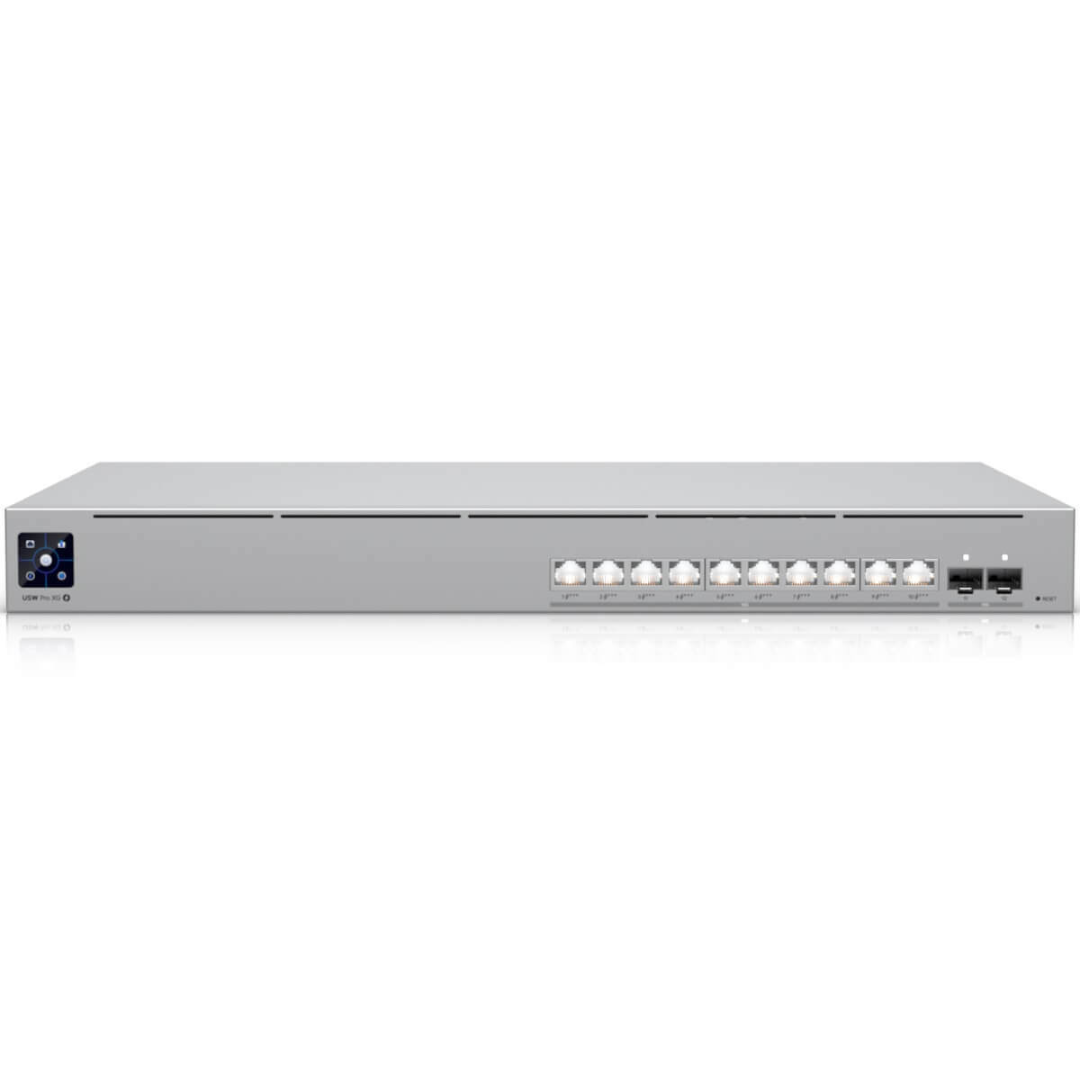 UniFi Pro XG 10 PoE · 400 W total budget
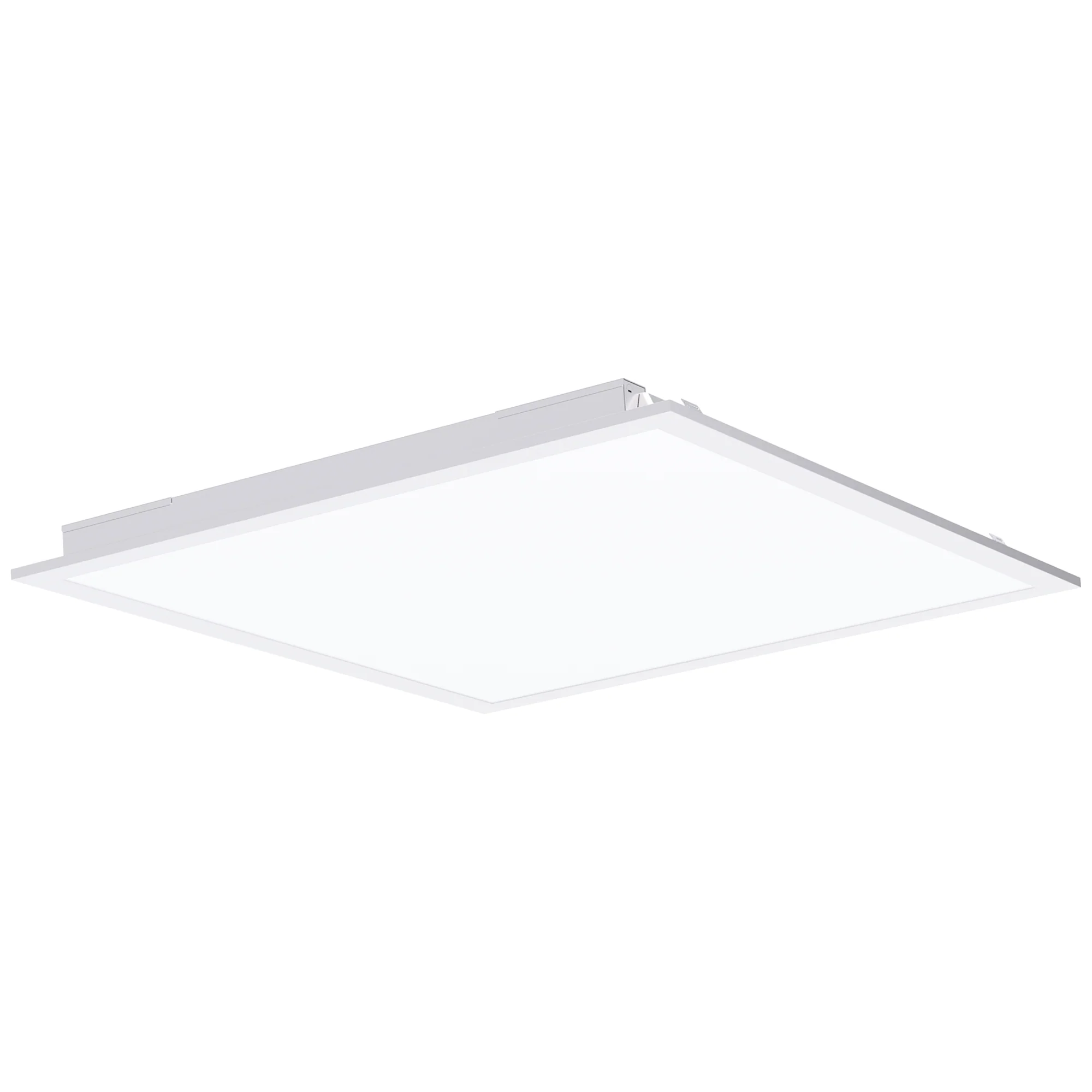 PoEWit PT-22 · two 35 W panels
| Role | Candidate component | Planning detail |
|---|---|---|
| SL-001 | Pro XG 10 PoEUSW-Pro-XG-10-PoE | 400 W aggregate PoE; 90 W maximum per eligible port |
| DRIVER | PoEWit UPD-1Exact driver variant pending | Manufacturer-specific constant-current LED driver |
| LIGHTS | Two PoEWit PT-22 panels35 W nominal per fixture | 2×2 LED ceiling panels; vendor kit includes matching 1:2 splitter |
| CABLE | 23 AWG solid-copper Cat6A4-pair tested Ethernet home run | Separate vendor-specified non-slim Cat6 driver-to-light leads, ≤25 ft |
| CONTROL | PoEWit lighting app / controlsFirmware and supported features TBD | Not controlled directly by UniFi Network |
Two fixtures rated at 35 W each total 70 W of LED output load. IEEE 802.3bt Type 4 planning provides 71.3 W guaranteed at the powered device under its allowed channel conditions. That leaves a theoretical 1.3 W before driver losses—not evidence that the two-panel configuration will work at worst-case cable length or full output. We must measure the actual driver input, conversion losses, startup and full-brightness behavior. If the combination cannot meet safe operating margins, it does not qualify.
Bench results must include observed measurements, evidence, the tester, the test date and any limitations. All critical checks must pass. Other exceptions require documented waivers, and an installation qualification also requires an appropriate pilot and project compliance review.
| Checks | Test area | What we verify | Current result |
|---|---|---|---|
| 05 | Documentation & equipment identity | Exact hardware revisions, firmware, factory-tuned driver, splitter, support and listing | Not tested |
| 03 | PoE negotiation & startup | Type 4 classification, cold start and recovery after reboot | Not tested |
| 05 | Electrical performance | Single/double panel load, driver overhead, input variations and sustained 8-hour operation | Not tested |
| 04 | Cabling & temperature | Short/long Cat6A channels, driver-to-fixture leads, bundles and environmental conditions | Not tested |
| 06 | Lighting controls | App onboarding, dimming, CCT, schedules, sensors and manual override | Not tested |
| 03 | Network & offline behavior | WAN loss, VLANs and UniFi Network application downtime | Not tested |
| 03 | Power continuity | AC loss/recovery; optional USP-RPS or Campus PSU tests only when in scope | Not tested |
| 02 | Scaling & headroom | Multiple drivers and whole-switch reserve budget | Not tested |
| 02 | Operations & service | As-built port labels and replacement/fault recovery | Not tested |
| 02 | Controlled pilot & final review | In-building trial and signed engineering disposition | Not tested |
Accepted evidence includes exact model and serial numbers, recorded firmware revisions, power measurements at the switch and powered device, cable test reports, startup logs, dimming and local-control demonstrations, offline operation, full-load reliability and a signed pilot report.
A manufacturer's individual product data sheet, a shopping listing or an assumption based only on IEEE 802.3bt compliance cannot substitute for a model-specific integration test.