
UniFi PoE Type 4 capability
Selected UniFi models publish 90 W maximum PSE output per supported port, subject to a separate whole-switch PoE budget.
Official UniFi tech specs ↗Select a low-wattage commercial fixture and quantity. Instantly compare eligible UniFi PoE switch models, driver counts, port limits and a clear power-budget breakdown.
Public manufacturer documentation can confirm electrical ratings, but it cannot establish that a particular UniFi switch and PoEWit driver have been jointly tested.
Selected UniFi models publish 90 W maximum PSE output per supported port, subject to a separate whole-switch PoE budget.
Official UniFi tech specs ↗PoEWit specifies 71.3 W guaranteed at the Type 4 powered device, fixture-specific driver channel limits, and Cat6 driver-to-light links of at most 25 ft.
Official UPD driver guide (PDF) ↗We have not obtained written manufacturer approval or a documented physical bench test of the UPD-1 with these exact UniFi models. Results remain planning estimates.
Ask PoEWit engineering ↗Choose a fixture and quantity to calculate LED demand, driver allocations, UniFi switch counts and reserved PoE capacity. These are preliminary engineering estimates; confirm complete system compatibility before ordering equipment.
What is required to unlock a tested combination? →*The IEEE Type 4 device-side guaranteed figure is not the same as the power available to LEDs after driver losses. The switch figure above is a conservative budget allocation, not measured electricity consumption. Aggregate planning wattage does not override individual switch port or PSU limits.
The review link carries only your selected light model, quantity and power-headroom setting into the consultation form. It does not confirm manufacturer interoperability or create an equipment order.
Compare switch quantities, per-port capacity, total PoE wattage and optional redundant-power modes using your selected fixtures, headroom and published equipment ratings.
External redundant DC supply and integrated hot-swappable PSUs are two different architectures. Neither adds PoE power to the switch nor substitutes for a battery UPS.
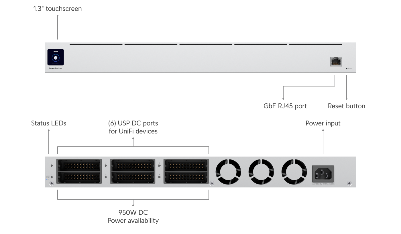
External DC power failover for supported switches with a USP-RPS input. Designed to support a failed switch power supply, not to provide battery runtime.
The shared rails limit how much load can actually fail over; a Pro XG 24 PoE can use up to 870 W including PoE at full rated output. Do not assume USP-RPS can back up a fully-loaded switch. Validate rail usage, loads, cabling and separate UPS sizing.
Official USP-RPS specifications ↗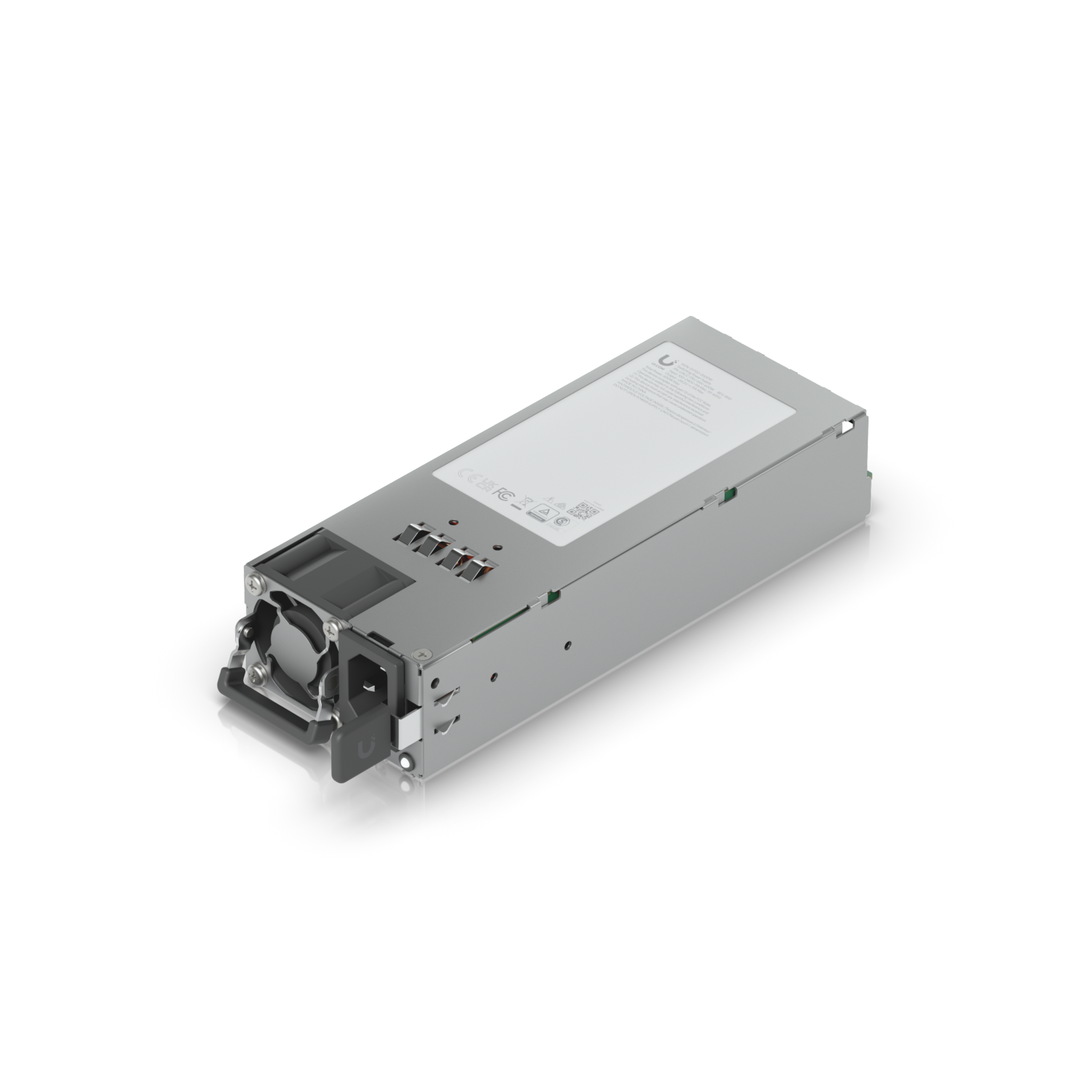
The Enterprise Campus 24 PoE uses two built-in modular, hot-swappable AC power supplies; it does not require or use the USP-RPS.
In this planner, switching on redundancy recalculates Campus capacity using the 450 W redundant-mode PoE budget. Optional 1,200 W replacement modules support other mode/voltage-specific budgets that must be designed separately.
Official Enterprise Campus specifications ↗Pro Max 24 PoE: 60 W per eligible PoE++ port, 400 W total budget. Pro Max 48 PoE: 64 W per PoE++ port, 720 W total. Both are excluded for these specific Type 4 UPD-1 configurations, even when the LED fixtures themselves are only 5–60 W.
Only move a combination to Manufacturer confirmed after receiving model-specific written confirmation; only mark it Bench tested after recording a successful physical test. None of the combinations below currently meets both milestones.
Confirm UPD-1/UPD-4 IEEE 802.3bt Type 4 negotiation with each specific UniFi model, firmware minimums, expected power class, and whether PoEWit cloud/app and LAN control work without PoEWit-branded switches.
Validate 90 W-capable port negotiation, driver startup and highest expected fixture brightness, switch total PoE budget, headroom and cable losses. Capture UniFi port telemetry and any driver reboot events.
Check Cat6 or better wire gauge, patch leads, PoE channel length, the PoEWit 25 ft driver-to-light limit, correct factory-tuned LED driver and required splitters; never mix home-run and daisy-chain splitters on one driver run.
Test power interruption/recovery, dimming and scene control, occupancy response, controller network access, and operation during internet loss after initial provisioning. Document model numbers and tested firmware versions.
Official references: PoEWit UPD Driver User Guide · UniFi PoE Availability and Modes · UniFi Support
A small LED fixture can be powered through a shared lighting driver. That driver has its own network power requirement, which is why the planner calculates the number of drivers before sizing switches.
For the PoEWit UPD-1 architecture, the manufacturer limits the Cat6 driver-to-light runs to 25 feet. Switch-to-driver links, cabling losses, network configuration, physical layout, emergency lighting requirements and controls require a project-specific review.
Fixture capacities and light wattages come from published PoEWit product data. Switch per-port and total budgets come from official UniFi specifications.
View PoEWit lighting models ↗UniFi Pro XG 10 specifications ↗UniFi Pro XG 24 specifications ↗UniFi Enterprise Campus specifications ↗Secure Luma is independently evaluating this equipment. There is no claim of authorization, manufacturer endorsement or laboratory-certified UniFi/PoEWit interoperability.Because this example uses a manufacturer-specified 90 W Type 4 PoE lighting driver that powers multiple low-wattage lights. The fixture rating does not equal the driver’s switch-port requirement.
No. The calculator reserves a conservative 90 W of switch PoE budget per selected UPD-1 driver. Actual electrical demand varies with dimming, connected fixtures, driver efficiency and other factors.
For this specific UPD-1 90 W Type 4 driver arrangement, the Pro Max 24 PoE provides up to 60 W per PoE++ port and the Pro Max 48 PoE up to 64 W. Neither meets the 90 W-per-port requirement.
No. Results are electrical-planning eligibility estimates based on published device and switch ratings. Confirm IEEE PoE negotiation, lighting drivers, cable distances, manufacturer approval and the control platform before purchasing.
Use the calculator for a planning baseline, then request a professional review of the actual light, driver, cabling and PoE design.